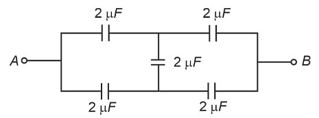
In the following circuit, the equivalent capacitance between terminal A and terminal B is :
- 2 µF
- 1 µF
- 0.5 µF
- 4 µF
The Correct Option is A
Solution and Explanation
To determine the equivalent capacitance between terminal A and terminal B in the given circuit, let's analyze the configuration step by step.
Circuit Analysis:
The circuit consists of four capacitors, each with a capacitance of 2 μF, arranged in a diamond shape as follows:
- Two capacitors are connected in series on the left side.
- Two capacitors are connected in series on the right side.
- These two series combinations are then connected in parallel between terminals A and B.
1. Series Combination on the Left Side:
Capacitors: 2 μF and 2 μF in series.
Equivalent capacitance for series:
$ \frac{1}{C_{\text{series}}} = \frac{1}{2} + \frac{1}{2} = 1 $
$ C_{\text{series}} = 1 \mu F $
2. Series Combination on the Right Side:
Capacitors: 2 μF and 2 μF in series.
Equivalent capacitance for series:
$ \frac{1}{C_{\text{series}}} = \frac{1}{2} + \frac{1}{2} = 1 $
$ C_{\text{series}} = 1 \mu F $
3. Parallel Combination of the Two Series Pairs:
The two 1 μF equivalent capacitors are now in parallel.
Equivalent capacitance for parallel:
$ C_{\text{parallel}} = 1 + 1 = 2 \mu F $
Final Answer:
The equivalent capacitance between terminal A and terminal B is: $ 2 \mu F $
Top Questions on Capacitors and Capacitance
- A parallel plate capacitor consisting of two circular plates of radius 10 cm is being charged by a constant current of 0.15 A. If the rate of change of potential difference between the plates is \( 7 \times 10^6 \, \text{V/s} \), then the integer value of the distance between the parallel plates is:
- JEE Main - 2025
- Physics
- Capacitors and Capacitance
- A capacitor, \( C_1 = 6 \, \mu F \), is charged to a potential difference of \( V_1 = 5 \, \text{V} \) using a 5V battery. The battery is removed and another capacitor, \( C_2 = 12 \, \mu F \), is inserted in place of the battery. When the switch 'S' is closed, the charge flows between the capacitors for some time until equilibrium condition is reached. What are the charges \( q_1 \) and \( q_2 \) on the capacitors \( C_1 \) and \( C_2 \) when equilibrium condition is reached?

- JEE Main - 2025
- Physics
- Capacitors and Capacitance
- A parallel plate capacitor of capacitance 1 μF is charged to a potential difference of 20 V. The distance between plates is 1 μm. The energy density between the plates of the capacitor is:
- JEE Main - 2025
- Physics
- Capacitors and Capacitance
Identify the valid statements relevant to the given circuit at the instant when the key is closed.

\( \text{A} \): There will be no current through resistor R.
\( \text{B} \): There will be maximum current in the connecting wires.
\( \text{C} \): Potential difference between the capacitor plates A and B is minimum.
\( \text{D} \): Charge on the capacitor plates is minimum.
Choose the correct answer from the options given below:- JEE Main - 2025
- Physics
- Capacitors and Capacitance
- The position of a particle moving on x-axis is given by \( x(t) = A \sin t + B \cos^2 t + Ct^2 + D \), where \( t \) is time. The dimension of \( \frac{ABC}{D} \) is:
- JEE Main - 2025
- Physics
- Capacitors and Capacitance
Questions Asked in NEET exam
- In some appropriate units, time (t) and position (x) relation of a moving particle is given by \(t = \alpha x^2 + \beta x\). The acceleration of the particle is :
- NEET (UG) - 2025
- Kinematic equations for uniformly accelerated motion
The output (Y) of the given logic implementation is similar to the output of an/a …………. gate.

- NEET (UG) - 2025
- Logic gates
- Two identical point masses P and Q, suspended from two separate massless springs of spring constants \(k_1\) and \(k_2\), respectively, oscillate vertically. If their maximum velocities are the same, the ratio of the amplitude of P to the amplitude of Q is :
- NEET (UG) - 2025
- Waves and Oscillations
- A particle of mass \(m\) is moving around the origin with a constant speed \(v\) along a circular path of radius \(R\). When the particle is at \( (0, R) \), its velocity is \( \mathbf{v} = -v \hat{\mathbf{i}} \). The angular momentum of the particle with respect to the origin is :
- NEET (UG) - 2025
- The Angular Momentum
- The radius of Martian orbit around the Sun is about 1.5 times the radius of the orbit of Mercury. The Martian year is 687 Earth days. Then which of the following is the length of 1 year on Mercury?
- NEET (UG) - 2025
- Kepler’s laws